As part of the project to control my metalworking lathe with a stepper motor (see https://www.martyndavis.com/?p=726), I’ve decided it would be useful to make some additional gears to step down the speed of the rotary encoder in relation to the lathe’s spindle.
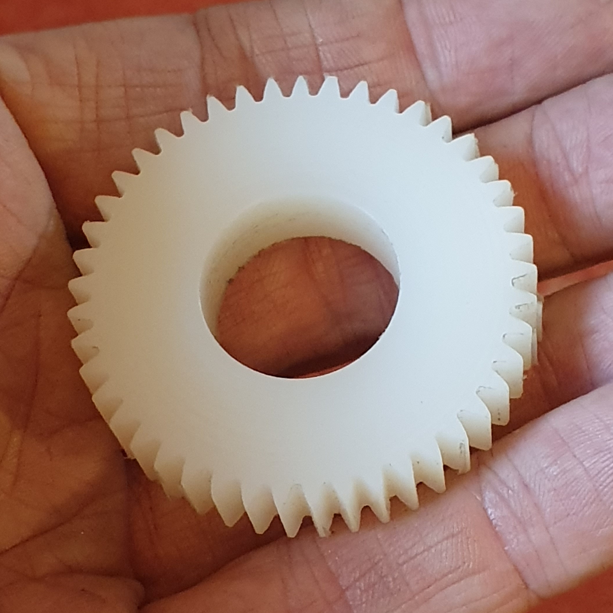
Here’s the first one I created (I haven’t cut a keyway in it yet).

To cut gears, typically people use a rotary table, which has a worm drive on it to allow for accurate turning of the workpiece via a handwheel which is marked with a vernier scale. I figured it would be easier to get a computer to do that for me.
Creating the software was simple, because I had all the components already created for the previous project. Unlike the lathe project, there are no microsecond-critical timing issues – just rotate, cut, rotate, and repeat until you’ve turned 360°. See it in action at https://youtu.be/4pt8MZhDIB4 – quite literally this was my first test, and it all just worked as expected.
The code can be found at https://github.com/md81544/electronicRotaryTable
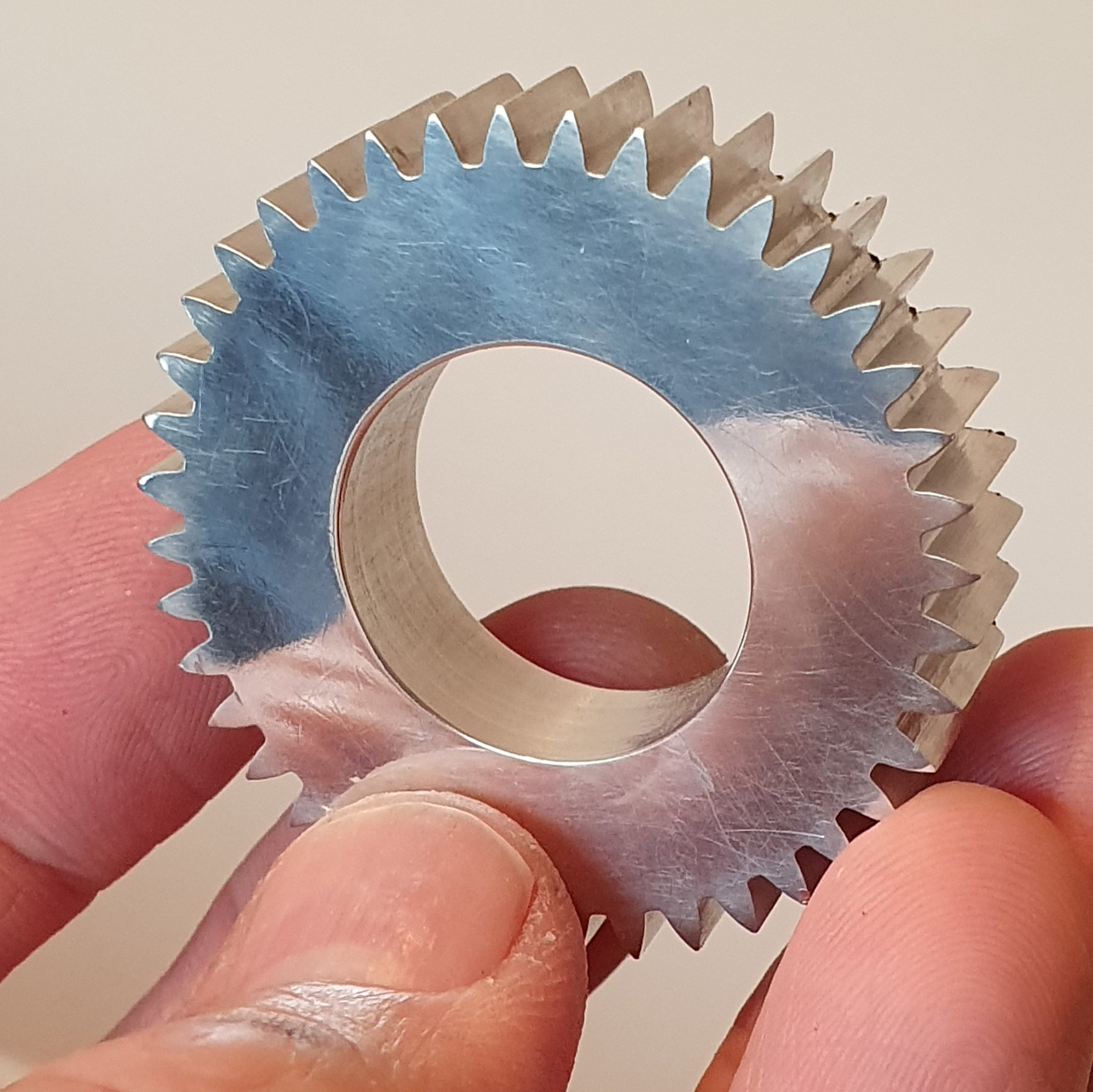
Update: here’s a new video showing the code in action for real, cutting an aluminium z40 spur gear. The result is shown below:
