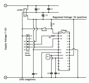
It was suggested to me that I should publish the actual circuit diagram of this project, together with a parts list. Here it is!
- Stripboard, at least 23 tracks long and 14 holes wide
- LM7805 voltage regulator
- C1 & C2 – 100μF 25V electrolytic capacitor
- C3 & C4 – 100nF ceramic disc capacitor
- C5 & C6 – 22pF ceramic disc capacitor
- R1 & R2 – 10K resistor
- X1 – 16MHz crystal
- Atmel ATMega168-20PU microcontroller*
- 28-Pin DIL Socket 0.3″ Pitch
- Momentary make push button
- 6 pin female header (you may want to make this male) **
- Hookup wire
* You could use a 328 rather than the 168 to give you extra capacity, it depends on the requirements of your application.
** As the board has no USB circuitry, to upload your programs you’ll need a USB to serial FTDI adapter or cable, e.g. http://www.sparkfun.com/products/10008 – this is the one I’m using, I’ve soldered male header pins onto it so it plugs directly into the serial header on the circuit we’ve made.
Alternatively there are complete cables, e.g.: http://www.sparkfun.com/products/9718 or http://www.oomlout.co.uk/usb-serial-cable-33v-p-232.html?zenid=b3297f914547cb4f9649318b7a95cf9a – these have a female six pin end, which is why you might want the header on the board to be male instead of female.
–
If the circuit doesn’t mean much to you, keep following the posts – all will become clear!
Next Post: http://www.martyndavis.com/?p=168

thanks for the parts list! if i still need to use serial over usb whenthe board is finished should i just connect the usb pins to the pins on te pin header?
You’ll need a USB to serial adapter – thanks for reminding me – I’ll add it now in the main post.
Edit: Done!
Do you happen to know any supplier in the US that carries stripboard? I’ve tried several times to find it here but none of the major vendors seem to carry it.
The serial connection works with good old fashioned RS232, correct? That’s all the FTDI cable does for you, right?
Hi Martyn, thanks for writing these up with photos, schematic and parts list. It’s good to have it all laid out like this.
Great work, and looking forward to more interesting posts!
@Notherstupidquestion: To be honest I’m not sure – it sounds plausible but I haven’t tried it (yet)! If you try it, let us know how you get on!
@crawford: have you tried RadioShack? Alternatively just search for “stripboard” or “veroboard” on ebay.com – lots of results come up! e.g. http://cgi.ebay.com/3-x-Small-StripBoard-94x53mm-Copper-Prototyping-Board-/320704440264?pt=LH_DefaultDomain_0&hash=item4aab7967c8#ht_1429wt_907 – HTH.
The long and thin 28pin socket for the atmega may not be easy to find, I wonder if putting a couple of 14pin sockets together endwise will work.
@NotherStupidQuestion:
The “good old fashioned RS232” uses different voltage levels and polarity:
logical zero= between +3 and +15 volts
logical one= between −3 and −15 volts
FTDI cable and ATMEGAxxx do:
logical zero= 0 volts
logical one= 5 volts
IC’s like MAX232 can translate between these two levels.
@coda: Yes it will, if your sockets are like mine. If they fit next to each other on the stripboard without skipping a hole they’ll be fine.
@RS232
I have built a couple of circuit to do this inversion and level shifting. Max232 is easier, but you can get away with using a couple of mosfet transistors.
Great resource!!! Thank you so much. Just an FYI, if you buy all the components from www.bitsbox.co.uk (excl. the USB) then the cost is under £8. I have no affiliation, bla bla bla, I just wanted to know how much I’d be saving by going down this route.
Awesome!
Hey, what software did you use to make the circuit diagram?
Hey Oscar, I used Photoshop… not very efficient, but it’s what I know… :)
Hi, great resource for an arduino newbie like myself :)
I just have the one small question, you mention that the 368 can be used in place of the 168, bitsbox list the 328, can this also be used, (for the extra 79p i may as well have twice the memory, lol) the datasheets look like they are the same layout (for the 168/328, but i cannot find a sheet for the 368?)