The first part of a (very) occasional series which follows my creation of a digital speedo for my motorcycle.
This is a project I’ve been thinking about, and working towards, on and off, for positively ages now. Work is really busy, and with a (still relatively) new daughter to fill in the gaps, my free time for the last eighteen months has been somewhat limited.
Apart from electronics projects, another work in progress is my motorcycle. It’s thirty-two years old, and, being a Honda, still runs really well. I do plan to strip it right down and re-paint the frame eventually. It also needs the occasional fix, for example the speedometer gave up the ghost last year, simply making a racket as the drive cable rotated around, presumably, a jammed shaft. I didn’t bother trying to fix it – I’d been thinking for a while how cool it would be to build an arduino-based circuit that counted wheel revolutions via a hall sensor and magnet to display speed.
My plans became more grandiose – I could also monitor engine revs, extrapolate the gear I’m in from the speed/revs, and have an electronic ignition lock. I actually built the first circuit. It worked really well on my desk, not so well on the bike. For one thing the ignition lock was based around a relay which would disconnect occasionally, stalling the bike. Also the 4×20 LCD display was too small and impossible to read in sunlight, and the rectangular project box that everything went in looked horrible on the bike.
I decided to pare back to essentials. Essentially I need a speedo, and I wanted it to look more in keeping. I decided I was going to use the original speedo housing, and add bright LEDs around the outside to show the speed, and have more in the middle to act as indicator, neutral and high-beam warning lights.
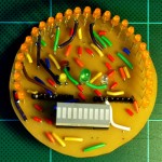
I started, with Eagle, to lay out the LEDs. I’d need twenty-seven to go around the outside to show speed in 5kph increments, another three for the warning lights, and then I thought maybe I’d add a ten-LED array (from Farnell) below them in case down the line I wanted to use it as a rudimentary tacho. Getting the LEDs arranged in a circle required a bit of a spreadsheet with sine and cosine calcs on it.
To drive 40 LEDs from one Arduino requires either a bit of jiggery pokery (Google “charlieplexing” if you’re interested) or, to cut the Gordian knot, simply buying a bit of extra hardware to do it. I opted for the latter given my lack of time. I went for the Maxim 7221 (from Farnell, the link to the item is: http://uk.farnell.com/maxim-integrated-products/max7221cng/ic-led-display-driver-8dig-24dip/dp/1593381). Information on linking this IC to an Arduino can be found here. It basically allows you to drive 64 LEDs from the one chip, and you can daisy-chain them together. The Arduino communicates with it via SPI, so it only ties up three pins no matter how many MAX7221s you have chained together.
I’ve been experimenting with etching my own circuit boards using the printer toner and HCl/H2O2 method with great success, so that’s what I used here.
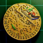
The LEDs effectively sit in an array – obviously physically they can be laid out any way – and I was using single-sided copper-clad board as it’s DIY. Usually when laying out a circuit in Eagle when you’ve only got one side (or layer) of copper means a bit of tweaking here and there to allow “nets” or tracks to connect where there’s no route for them to do so – normally I’ll add a few zero-ohm resistors in the board layout to connect them (and use plain wire, of course, when building). I found laying this array out impossible like this though, so the easiest solution was to tell Eagle I was using double-sided board, and tell it to favour the bottom side, and I figured I’d just add wire on the top where the tracks were meant to be. That ended up a bit of a rat’s nest when I came to build it!
I’m not proud of how this looks – but it works, which I was pleased with. I think if I had to lay out something like this with so many top-side connections again I’d experiment with using two single-sided boards and sandwiching them together, linked with through pins (“vias“) where needed.
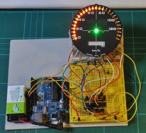
To control the 7221, I used the LedContol library – which makes addressing each individual LED on the matrix as easy as just specifying a row and column. You can also control the intensity of the LEDs as well, which is nice. Here’s the thing running. The photo doesn’t do the display justice – it should be much easier to see the LEDs even in bright sunlight. The green LED in the middle will be the neutral indicator.
Next time (when I get a chance!!) I’ll document building the “veroboarduino” driver and handling the inputs from the hall sensor to count wheel rotations and pick up the neutral, high-beam and indicator warning signals.


Cool! I made something like that for my car.
http://youtu.be/A_9PThXffyM
Don’t beat yourself up, it looks awesome. Nice job of it.
I’m there with you on this awesome project! I have an 83′ Honda 750. Might look into this when I have some free time!
YES! This is exactly what I need for my old british lathe. Thank you for sharing!
Are you planning to release the design files for this project? It looks terrific.
Hi Wardy, thanks for the kind comments, yes, I’ll put up all the Eagle files soon. I’ve just today laid out the tracks for the driver circuit, which has the MAX7221 on it together with an ATMega, power, three optocouplers and three headers. Quite a tight squeeze! That’ll be the next post once I’ve got it working :)
How did/will you deal with the input signal from the Hall effect sensors? Has someone written software for the Arduino to do this already?
Hi Arthur, I’ve already written this for the first prototype version. It’s basically simply adding an interrupt to the input from the Hall effect sensor, with a volatile counter. Then when I want the speed, I can see how many revolutions have taken place within the time period since last check. I also did a bit of smoothing as my first display was numeric. With this display I probably won’t need the smoothing. I’ll put the code up too soon!
Martyn
Nice work. Thanks for sharing. I need to do something similar for my Yamaha 650 of the same vintage. I need to figure out how to handle the odometer task too.
Cheers.
Hello, I too have Suzuki Bandit250 motorcycle, but I have no speedometer, on it I am interested to help you with development of a speedometer, and a tachometer, you could send me the file of the program Arduino code on my e-mail kree@bk.ru
Honda motorcycles really last for a long time and I can tell that because I own one. I buy my motorbike accessories in Melbourne and those are really sturdy. I am interested to see your documentation about that veroboarduino because it looks pretty nifty.
Hi Martyn!
Your Speedo looks really amazing- any pictures with the housing?
I stumpled over your side, coz I had exactly the same in mind for my Suzi. Is there a reason for using a reed sensor? Still “mechanical”… originally I wanted to use a optical sensor, e.g. disected mouse…
And for the display itself maybe an charliplexed LED shield (just have it) for big shiny fancy numbers… :D
Anyhow, I’m just starting… it’ll be my second Arduino project (first was a remote controlled preamp with display etc)- would you kindly release the code for your Speedo, I’m not the big programmer, rather builder!
Regards,
Ralf
@ VROOM:
Is it posseble to become a print layout and list of materials from you’re project.
I love it.
Best regards,
Johan
Hlo sir plz send me this Project circuit board schematic
My whatsapp number : +917973987345
My email : power77.tech@gmail.com
very very nice piece you made. Very impressive. You need to give yourself more credit!!!.